Cele:
- R1 i R3 – dodaj trasy statyczne do sieci 10.0.12.0/29 oraz 10.0.23.0/29.
- Skonfiguruj EBGP pomiędzy AS 65001 a AS 65003. Upewnij się, że sesja BGP została nawiązana. Rozgłoś sieci 1.1.1.0/24 oraz 3.3.3.0/24 w BGP. Sprawdź czy R1 i R3 mają z nimi pełną łączność.
Adresy IP routerów:
R1
| Interfejs | IP |
|---|---|
| FastEthernet 0/0 | 10.0.12.1/29 |
| Loopback 0 | 1.1.1.1/24 |
R2
| Interfejs | IP |
|---|---|
| FastEthernet 0/0 | 10.0.12.2/29 |
| FastEthernet 1/0 | 10.0.23.2/29 |
R3
| Interfejs | IP |
|---|---|
| FastEthernet 0/0 | 10.0.23.3/29 |
| Loopback 0 | 3.3.3.3/24 |
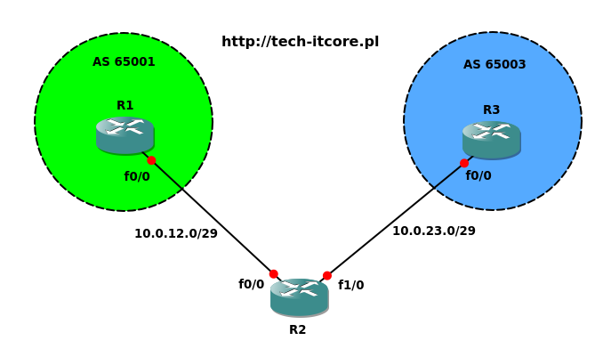
Schemat sieci:
Router: 3640
IOS: c3640-jk9o3s-mz.124-16a.bin
Rozwiązanie
R1 i R3 – dodaj trasy statyczne do sieci 10.0.12.0/29 oraz 10.0.23.0/29.
W zadaniu skonfigurujemy EBGP pomiędzy routerami R1 i R3. Definiując sąsiadów musimy mieć pewność, że routery mają ze sobą łączność. Najprostszym sposobem będzie dodanie statycznych wpisów do sieci 10.0.23.0/29 na R1 oraz do sieci 10.0.12.0/29 na R3:
R1(config)#ip route 10.0.23.0 255.255.255.248 fastEthernet 0/0
R3(config)#ip route 10.0.12.0 255.255.255.248 fastEthernet 0/0
Dla pewności ping z R1 do R3:
R1#ping 10.0.23.3

Type escape sequence to abort.
Sending 5, 100-byte ICMP Echos to 10.0.23.3, timeout is 2 seconds:
!!!!!
Success rate is 100 percent (5/5), round-trip min/avg/max = 12/15/24 ms
Skonfiguruj EBGP pomiędzy AS 65001 a AS 65003. Upewnij się, że sesja BGP została nawiązana. Rozgłoś sieci 1.1.1.0/24 oraz 3.3.3.0/24 w BGP. Sprawdź czy R1 i R3 mają z nimi pełną łączność.
Zaczynamy standardowo od konfiguracji BGP na routerach R1 i R3. Od razu też rozgłosimy sieci z interfejsów Loopback:
R1(config)#router  bgp 65001
R1(config-router)#neighbor 10.0.23.3 remote-as 65003
R1(config-router)#network 1.1.1.0 mask 255.255.255.0
R3(config)#router  bgp 65003
R3(config-router)#neighbor 10.0.12.1 remote-as 65001
R3(config-router)#network 3.3.3.0 mask 255.255.255.0
Zobaczmy status BGP:
R1#show ip bgp summary
BGP router identifier 1.1.1.1, local AS number 65001
BGP table version is 2, main routing table version 2
1 network entries using 117 bytes of memory
1 path entries using 52 bytes of memory
2/1 BGP path/bestpath attribute entries using 248 bytes of memory
0 BGP route-map cache entries using 0 bytes of memory
0 BGP filter-list cache entries using 0 bytes of memory
BGP using 417 total bytes of memory
BGP activity 2/1 prefixes, 2/1 paths, scan interval 60 secs

Neighbor        V    AS MsgRcvd MsgSent   TblVer  InQ OutQ Up/Down  State/PfxRcd
10.0.23.3       4 65003       1       1        0    0    0 never    Idle
State/PfxRcd ma wartość Idle. Routery nie zestawiły ze sobą sesji BGP. Nie ma też informacji o rozgłaszanych sieciach w BGP:
R1#show ip bgp
BGP table version is 2, local router ID is 1.1.1.1
Status codes: s suppressed, d damped, h history, * valid, > best, i - internal,
              r RIB-failure, S Stale
Origin codes: i - IGP, e - EGP, ? - incomplete

   Network          Next Hop            Metric LocPrf Weight Path
*> 1.1.1.0/24       0.0.0.0                  0         32768 i
Domyślnie EBGP pozwala na zestawienie sesji między dwoma routerami tylko jeżeli mają ze sobą bezpośrednie połączenie. W podanym przykładzie założenie to nie jest spełnione, ponieważ pomiędzy R1 i R3 mamy jeden dodatkowy węzeł (router R2). Pakiety generowane przez EBGP mają wartość TTL (Time To Live) równą 1. Problem można łatwo rozwiązać korzystając z opcji ebgp-multihop przy definicji sąsiada:
R1(config)#router  bgp 65001
R1(config-router)#neighbor 10.0.23.3 ebgp-multihop 2
R3(config)#router  bgp 65003
R3(config-router)#neighbor 10.0.12.1 ebgp-multihop 2
Zwiększyliśmy limit z 1 do maksymalnie 2 hopów. Taka ilość powinna wystarczyć do nawiązania sesji BGP pomiędzy R1 i R3.
R1#show ip bgp summary
BGP router identifier 1.1.1.1, local AS number 65001
BGP table version is 3, main routing table version 3
2 network entries using 234 bytes of memory
2 path entries using 104 bytes of memory
3/2 BGP path/bestpath attribute entries using 372 bytes of memory
1 BGP AS-PATH entries using 24 bytes of memory
0 BGP route-map cache entries using 0 bytes of memory
0 BGP filter-list cache entries using 0 bytes of memory
BGP using 734 total bytes of memory
BGP activity 2/0 prefixes, 3/1 paths, scan interval 60 secs

Neighbor        V    AS MsgRcvd MsgSent   TblVer  InQ OutQ Up/Down  State/PfxRcd
10.0.23.3       4 65003      34      34        3    0    0 00:30:13        1
Widzimy, że BGP działa. Router 10.0.23.3 rozgłasza jeden prefiks. Zobaczmy tablicę routingu:
R1#show ip route bgp
     3.0.0.0/24 is subnetted, 1 subnets
B       3.3.3.0 [20/0] via 10.0.23.3, 00:31:03
Wpis do sieci jest. Możemy przetestować łączność. Najpierw jednak musimy dodać statycznie trasy do 1.1.1.0/24 oraz 3.3.3.0/24 także na R2, w przeciwnym razie sieci te wciąż nie będą dostępne dla R1 i R3:
R1#ping 3.3.3.3 source loopback 0

Type escape sequence to abort.
Sending 5, 100-byte ICMP Echos to 3.3.3.3, timeout is 2 seconds:
Packet sent with a source address of 1.1.1.1
U.U.U
Success rate is 0 percent (0/5)
R2(config)#ip route 1.1.1.0 255.255.255.0 fastEthernet 0/0
R2(config)#ip route 3.3.3.0 255.255.255.0 fastEthernet 1/0
Ponownie ping:
R1#ping 3.3.3.3 source loopback 0

Type escape sequence to abort.
Sending 5, 100-byte ICMP Echos to 3.3.3.3, timeout is 2 seconds:
Packet sent with a source address of 1.1.1.1
!!!!!
Success rate is 100 percent (5/5), round-trip min/avg/max = 28/39/44 ms
Ping przeszedł, zadanie wykonane. Zapraszamy do innych zadań z sekcji Cisco Labs na naszym blogu oraz czekamy na Wasze komentarze.


0 Komentarze.